5G / NR: From Broadband to Mission-Critical Connectivity
5G New Radio (NR) launched commercially in 2019 in South Korea and the US. Unlike previous generations defined by a single use case, 5G is designed for three fundamentally different scenarios: ultra-fast broadband (eMBB), ultra-low latency (URLLC), and massive machine connectivity (mMTC). Its service-based core architecture (5GC) and network slicing capability represent the most radical redesign of mobile core networks since GSM.
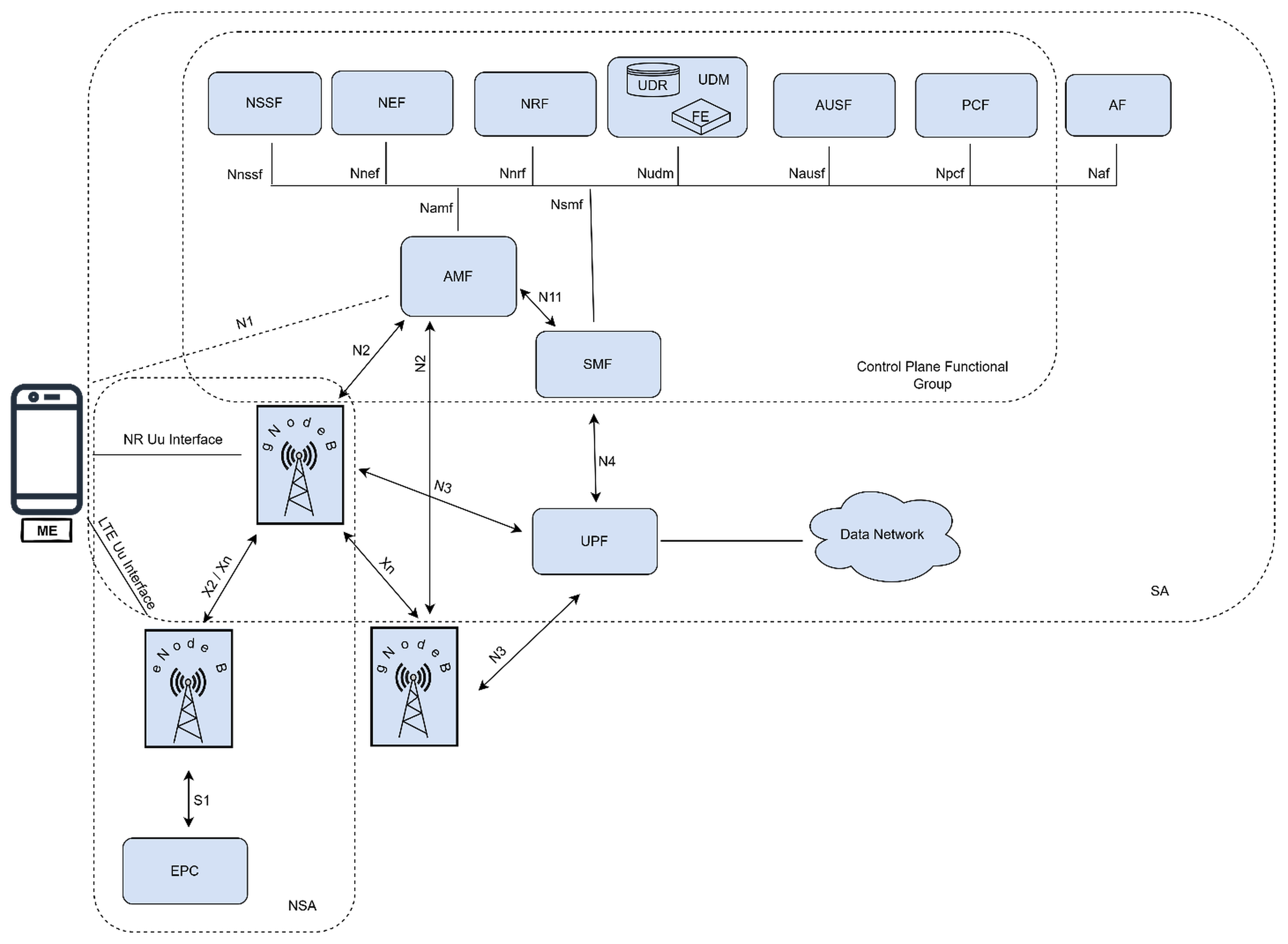
5G Architecture
Five Logical Layers — UE, RAN, and 5GC
The UE (also referred to as the ME — Mobile Equipment) is the device used by the subscriber: a smartphone, tablet, CPE, or IoT module. In Standalone (SA) mode the UE connects to a gNB over the NR Uu air interface. In Non-Standalone (NSA) mode, the UE maintains a simultaneous connection to both an eNB (LTE, LTE Uu) and a gNB — the eNB anchors the control plane while the gNB adds 5G data capacity.
The gNB is the 5G radio access node — it transmits and receives NR signals and terminates the NR Uu interface toward the UE. Each gNB connects to the AMF via the N2 interface (control plane) and to the UPF via N3 (user plane). Adjacent gNBs communicate directly over the Xn interface for handover and coordination. In NSA mode, an eNB connects to a gNB via X2/Xn for dual-connectivity.
The 5G Core replaces the LTE EPC with a cloud-native, microservices-based design. All control-plane network functions (NFs) expose HTTP/2 REST APIs on a Service-Based Interface (SBI) and register with the NRF so other functions can discover them dynamically. Key functions visible in the architecture:
- AMF — Access and Mobility Management Function; the central control-plane anchor. Handles UE registration, NAS signalling, mobility management, and paging. The UE has a logical N1 interface to the AMF. The gNB connects to the AMF via N2. The AMF communicates with the SMF via N11.
- SMF — Session Management Function; manages all PDU sessions: allocates IP addresses, selects and controls the UPF, and enforces QoS policies. Communicates with the UPF over N4.
- UDM — Unified Data Management; stores subscriber profiles, authentication credentials, and authorised services. Backed by the UDR (Unified Data Repository) with a Front End (FE) separating application logic from storage.
- AUSF — Authentication Server Function; executes the 5G-AKA and EAP-AKA' authentication procedures on behalf of the AMF, interacting with the UDM for key material.
- PCF — Policy Control Function; provides unified policy rules for session management (QoS, charging) and access control, replacing the PGW-c/PCRF of LTE.
- NSSF — Network Slice Selection Function; selects the appropriate Network Slice Instance (NSI) and AMF set for a UE based on its NSSAI (slice identifier).
- NEF — Network Exposure Function; securely exposes 5G network capabilities and events to authorised third-party applications and AF.
- NRF — Network Repository Function; the service registry — all NFs register here and discover each other via NRF queries.
- AF — Application Function; an application-layer entity (may be operator-owned or third-party) that interacts with the 5GC via NEF or directly with PCF/SMF for QoS influence.
The UPF is the sole user-plane forwarding node in the 5GC — it carries all actual subscriber data packets. The gNB tunnels user-plane traffic to the UPF via N3 (GTP-U); the SMF controls the UPF via the N4 interface (PFCP protocol) to install packet detection, forwarding, and QoS enforcement rules. The UPF connects to the external Data Network (e.g., the internet or an enterprise network) via the N6 interface. UPFs can be deployed centrally (cost-efficient) or pushed to the network edge (low latency for URLLC and MEC).
In NSA deployment, the LTE eNB continues to serve as the control-plane anchor — it connects to the existing EPC via the S1 interface for mobility and signalling. A 5G gNB is added as a secondary node, connected to the eNB via X2/Xn. The gNB provides additional user-plane capacity (N3 to UPF or via the S-GW/PGW depending on option), but all registration, paging, and handover are still handled by the LTE/EPC path. NSA (Option 3x) was the first deployment mode used by most operators, allowing rapid 5G launch without replacing the LTE core.
The 5G architecture supports both SA (Standalone) and NSA (Non-Standalone) deployment modes, as shown in the diagram. SA mode uses the native 5GC with AMF, SMF, UPF and the full service-based interface mesh. NSA mode anchors the control plane on the LTE eNB and EPC while the gNB adds NR radio capacity. Interfaces N1, N2, N3, N4, N11, Xn, and the SBI (Namf, Nsmf, Nudm, Nausf, Npcf, Nnssf, Nnef, Nnrf, Naf) are all labelled in the figure.
Abbreviations
| Abbreviation | Full Form | Abbreviation | Full Form |
|---|---|---|---|
| UE | User Equipment | ME | Mobile Equipment |
| gNB | gNodeB (5G NR Base Station) | eNB | eNodeB (LTE Base Station) |
| NR | New Radio | NR Uu | 5G Air Interface (UE ↔ gNB) |
| LTE Uu | LTE Air Interface (UE ↔ eNB) | N1 | UE ↔ AMF (logical NAS) |
| N2 | gNB ↔ AMF | N3 | gNB ↔ UPF (GTP-U tunnel) |
| N4 | SMF ↔ UPF (PFCP) | N11 | AMF ↔ SMF |
| Xn | gNB ↔ gNB | X2 | eNB ↔ gNB (NSA dual-connectivity) |
| S1 | eNB ↔ EPC (NSA) | N6 | UPF ↔ Data Network |
| AMF | Access and Mobility Management Function | SMF | Session Management Function |
| UPF | User Plane Function | UDM | Unified Data Management |
| UDR | Unified Data Repository | FE | Front End (UDM application logic) |
| AUSF | Authentication Server Function | PCF | Policy Control Function |
| NSSF | Network Slice Selection Function | NEF | Network Exposure Function |
| NRF | Network Repository Function | AF | Application Function |
| 5GC | 5G Core Network | EPC | Evolved Packet Core (LTE core) |
| SBA | Service-Based Architecture | SBI | Service-Based Interface (HTTP/2) |
| PDU | Protocol Data Unit (session type in 5G) | PFCP | Packet Forwarding Control Protocol |
| NSA | Non-Standalone (LTE anchor + 5G NR) | SA | Standalone (native 5GC) |
| MEC | Multi-access Edge Computing | NSI | Network Slice Instance |
| NSSAI | Network Slice Selection Assistance Information | GTP-U | GPRS Tunnelling Protocol (User Plane) |
Three Core Use Cases
Targets human-centric broadband applications: 4K/8K streaming, fixed wireless access (FWA), AR/VR, and dense stadium/event deployments. Peak theoretical downlink: 20 Gbps. Real-world mmWave deployments achieve 1–4 Gbps; sub-6 GHz deployments typically 200–1000 Mbps. Sub-6 GHz 5G covers wide areas; mmWave (24–100 GHz) delivers extreme capacity at short range (100–200 m).
Targets machine-to-machine and mission-critical applications: factory automation, remote surgery, autonomous vehicles, and smart grid control. Target latency: <1 ms over-the-air; 99.999% reliability. Achieves this through mini-slots (as short as 0.125 ms), pre-emption of eMBB traffic, and redundant multi-path transmission.
Targets low-power, wide-area IoT: smart meters, agriculture sensors, asset trackers, and city infrastructure. Target: 1 million devices per km². 5G NR-Light (Rel-17 RedCap) addresses mid-tier IoT; LTE-based NB-IoT and LTE-M are the primary mMTC technologies in current 5G networks, operating as part of the 5G ecosystem.
5G New Radio — The Air Interface
- Flexible numerology — 5G NR uses a configurable subcarrier spacing (SCS) called numerology µ: 15 kHz (µ=0, like LTE), 30 kHz (µ=1), 60 kHz (µ=2), 120 kHz (µ=3), 240 kHz (µ=4). Higher SCS reduces slot duration, enabling lower latency and supporting mmWave frequencies
- FR1 (sub-6 GHz) and FR2 (mmWave) — FR1 covers 410 MHz–7.125 GHz (broad coverage, similar propagation to LTE); FR2 covers 24.25–52.6 GHz (extreme capacity, very limited range and penetration, requires beamforming)
- Channel bandwidth up to 400 MHz — a single 5G NR carrier can be up to 100 MHz wide in FR1 and 400 MHz in FR2, compared to 20 MHz maximum in LTE
- CP-OFDM downlink and DFTS-OFDM uplink — same OFDM family as LTE but with flexible CP overhead; DFTS-OFDM on the uplink reduces PAPR when continuous coverage is needed
Massive MIMO and Beamforming
5G NR base stations (gNBs) routinely use 64 transmit and 64 receive antenna elements in the active antenna unit (AAU). More antennas enable more simultaneous spatial layers (MU-MIMO) — a single gNB can serve 8–16 UEs simultaneously on the same time-frequency resource, multiplying cell capacity without additional spectrum.
With a 2D antenna array, the gNB can steer beams in both horizontal and vertical directions (Full-Dimension MIMO). This allows the network to focus energy precisely at each UE's location, increase signal strength, reduce interference to neighbouring cells, and serve users on different floors of a building simultaneously — critical for dense urban and indoor deployments.
Network Slicing
Network slicing is 5G's most transformative architectural feature — it allows a single physical 5G network to be divided into multiple isolated logical networks, each customised for a specific use case or customer:
- Each slice has dedicated resources — separate AMF/SMF/UPF instances (or shared with isolation), radio resource quotas, and QoS policies; one slice's failure or overload cannot affect others
- NSSAI — Network Slice Selection Assistance Information — a standardised identifier carried in NAS messages; the AMF uses it to route the UE to the correct slice at attach time
- Example slices — a public safety slice (guaranteed URLLC bandwidth), a consumer eMBB slice (best-effort broadband), and a private enterprise slice (isolated, dedicated capacity) can all run on the same infrastructure simultaneously
- Requires end-to-end orchestration — slices must be provisioned across RAN (via RAN slicing), transport, and core; this typically requires an NFVO/MANO system or a cloud orchestrator like Kubernetes with 5G-aware scheduling
NSA vs SA Deployment Modes
The initial deployment mode used by most operators. 5G NR provides the additional radio capacity (data plane) while LTE eNBs remain the control-plane anchor — UE registration, mobility, and paging all use the existing LTE/EPC infrastructure. This allowed rapid nationwide 5G launch without replacing the LTE core network.
The target architecture: 5G NR gNBs connect directly to the native 5GC (AMF, SMF, UPF). Unlocks all 5G features — network slicing, URLLC, edge computing, and full control-plane independence. Requires deploying the new 5GC alongside gNBs, which is a larger investment. SA deployments are growing from 2022 onward.
5G's Significance
- Industry 4.0 enabler — URLLC and private 5G networks are enabling wireless factory automation, robot control, and real-time quality inspection at scales impossible with Wi-Fi or LTE
- Fixed Wireless Access (FWA) — 5G replaces DSL and cable broadband in underserved areas; home routers using 5G mmWave or sub-6 GHz deliver gigabit speeds without digging trenches
- Cloud-native telecom — the 5GC's containerised microservices model brings DevOps practices to telco infrastructure; operators can update individual functions independently and scale horizontally
- Security improvements — 5G added SUPI/SUCI (conceals IMSI over the air), subscription concealment via ECIES, and enhanced NAS integrity protection; IMSI catchers are significantly harder to execute
- Platform for 6G research — AI-native network management, integrated sensing, and reconfigurable intelligent surfaces (RIS) are being prototyped on 5G infrastructure as precursors to 6G