3G / UMTS: The First Mobile Broadband Era
Launched commercially in Japan in 2001, 3G (UMTS) introduced real mobile broadband — web browsing, video calls, and eventually speeds exceeding 42 Mbps with HSPA+. It replaced GSM's TDMA radio with W-CDMA, introduced mutual authentication via AKA, and laid the architectural foundation for the all-IP world that 4G would complete.
What Changed from 2G to 3G
- New radio access technology — W-CDMA replaced TDMA, using a 5 MHz channel and spreading codes instead of time slots; all users transmit simultaneously on the same frequency
- Dual-domain core network — the core was cleanly split into Circuit-Switched (CS) for voice and Packet-Switched (PS) for data, both running on shared physical infrastructure
- Mutual authentication — the AKA protocol means the UE can verify it is talking to a genuine network, closing the IMSI-catcher vulnerability of GSM
- USIM replaces SIM — the Universal SIM card stores 3G credentials and runs the AKA algorithms; backward-compatible with 2G networks
- Video calls over CS — the 64 kbps CS bearer enabled real-time face-to-face video calls for the first time on a mobile network
3G Architecture
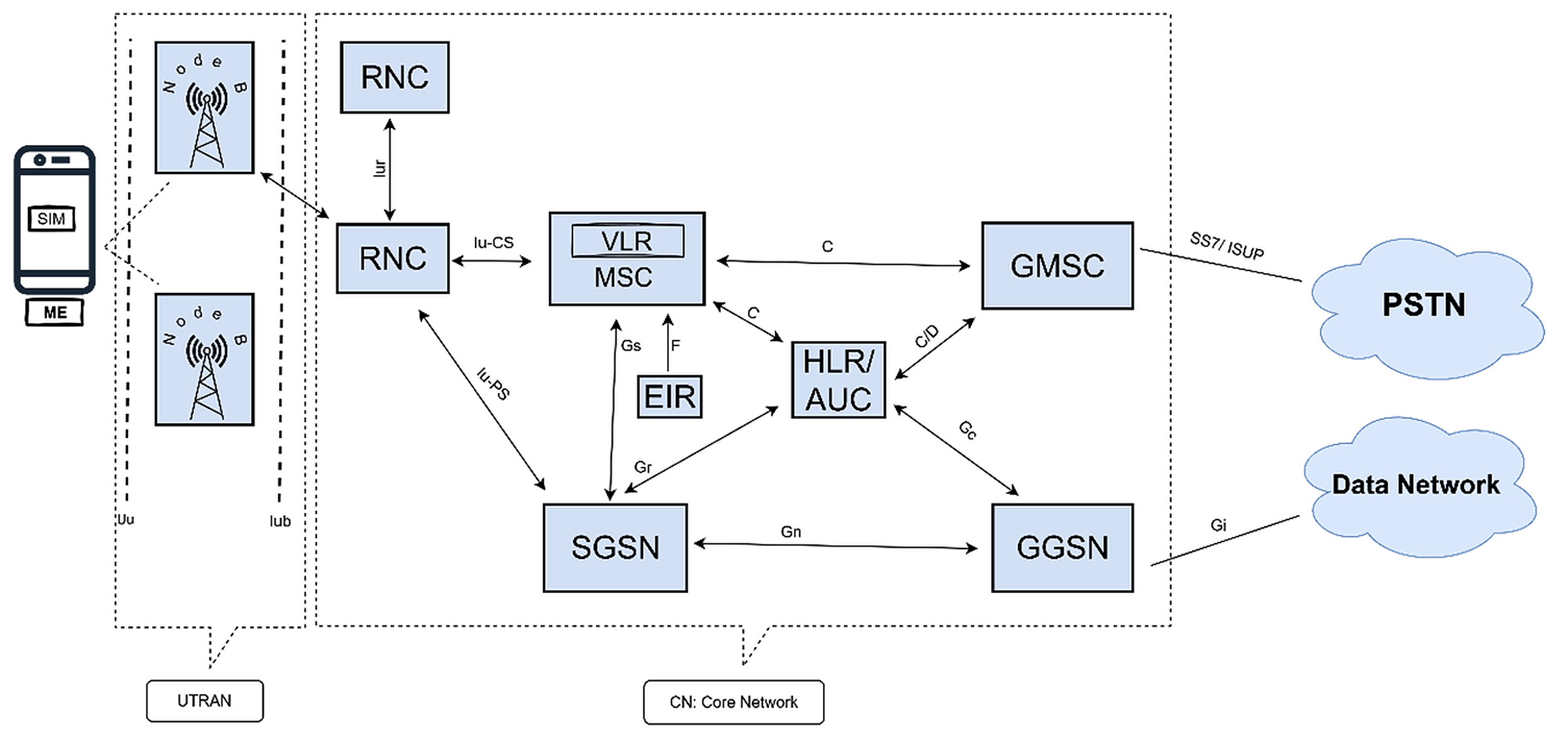
UTRAN — The Radio Access Network
UMTS Terrestrial Radio Access Network (UTRAN) sits between the UE and the core network. It replaced the 2G BTS/BSC pair with two new node types:
Node B is the physical antenna site — the 3G equivalent of a 2G BTS. It transmits and receives W-CDMA radio signals to/from UEs over the Uu interface. Node B intelligence is intentionally minimal; all scheduling, handover decisions, and routing are controlled by the RNC above it via the Iub interface.
The RNC manages one or more Node Bs. It handles soft handover (a UE can be connected to two Node Bs simultaneously, with signals combined at the RNC), uplink/downlink power control, and RRC (Radio Resource Control) state management. The RNC connects to the core via two Iu interfaces — Iu-CS toward the MSC and Iu-PS toward the SGSN.
Abbreviations
| Abbreviation | Full Form | Abbreviation | Full Form |
|---|---|---|---|
| UE | User Equipment | UTRAN | UMTS Terrestrial Radio Access Network |
| ME | Mobile Equipment | CN | Core Network |
| USIM | Universal Subscriber Identity Module | PSTN | Public Switched Telephone Network |
| Node B | 3G Base Station | Uu | Air Interface (UE ↔ Node B) |
| RNC | Radio Network Controller | Iub | Interface (Node B ↔ RNC) |
| MSC | Mobile Switching Center | Iur | Interface (RNC ↔ RNC) |
| VLR | Visitor Location Register | Iu-CS | RNC ↔ MSC (Circuit Switched) |
| HLR | Home Location Register | Iu-PS | RNC ↔ SGSN (Packet Switched) |
| AUC | Authentication Center | Gs | Interface (SGSN ↔ MSC/VLR) |
| EIR | Equipment Identity Register | Gr | Interface (SGSN ↔ HLR) |
| GMSC | Gateway Mobile Switching Center | Gn | Interface (SGSN ↔ GGSN) |
| SGSN | Serving GPRS Support Node | Gc | Interface (GGSN ↔ HLR) |
| GGSN | Gateway GPRS Support Node | Gi | Interface (GGSN ↔ Data Network) |
| W-CDMA | Wideband Code Division Multiple Access | C/D | Interface (GMSC/MSC ↔ HLR) |
| SS7/ISUP | Signaling System 7 / ISDN User Part | F | Interface (MSC ↔ EIR) |
W-CDMA Radio Technology
Wideband Code Division Multiple Access discards TDMA's time slicing in favour of spreading codes. Every user transmits across the full 5 MHz channel at the same time — users are separated by their unique spreading code:
- 5 MHz channel bandwidth — 25× wider than a GSM channel, enabling far higher per-user data rates
- 3.84 Mcps chip rate — the speed at which spreading codes are generated; chips per second is much higher than data bits per second, which is how the signal is spread across bandwidth
- Variable spreading factor (SF 4–512) — a lower SF means more data bits per chip (higher throughput) at the cost of fewer simultaneous users; the RNC allocates SF per UE based on demand
- Soft handover — a UE can maintain connections to two or more Node Bs simultaneously; both signals are combined in the RNC (macro diversity), improving quality at cell edges
- Fast closed-loop power control at 1,500 Hz — transmit power adjusts 1,500 times per second in both directions to maintain consistent signal quality while minimising interference
Core Network — CS and PS Dual Domains
Handles voice and video calls over guaranteed, reserved circuits — the same model as 2G but extended to support the 3G radio. Key nodes: the MSC (Mobile Switching Centre) routes calls; the GMSC interfaces with the PSTN for calls to/from landlines; the HLR remains the subscriber master database.
Reuses and extends the GPRS packet core from 2.5G. The SGSN (Serving GPRS Support Node) tracks UE location and delivers packets between UTRAN and GGSN. The GGSN (Gateway GPRS Support Node) assigns IP addresses, applies QoS policies, and routes data to/from external networks. Both nodes connect to UTRAN via the Iu-PS interface.
HSPA Evolution — 3.5G and 3.75G
W-CDMA's original 384 kbps data rate was quickly superseded by two major software and hardware upgrades that ran on the same UTRAN infrastructure:
Introduced a new high-speed downlink channel (HS-DSCH) with adaptive modulation (QPSK and 16-QAM), fast link adaptation, and Node B-side scheduling. Peak downlink: 14.4 Mbps. Users experienced practical speeds of 1–5 Mbps in real networks.
Added a high-speed uplink channel (E-DCH) with Node B-controlled scheduling. Peak uplink: 5.76 Mbps. Critical for symmetric applications like video calling, file uploads, and push email.
Added 64-QAM modulation and 2×2 MIMO on the downlink, pushing theoretical peak to 42 Mbps per carrier. Dual-carrier HSPA+ could reach 84 Mbps by aggregating two 5 MHz carriers. Many operators marketed HSPA+ as “4G” before true LTE deployments.
All HSPA improvements were deployed as firmware/hardware upgrades to existing Node Bs and RNCs — operators did not need to rebuild their radio access networks. This made HSPA the most cost-effective mobile data upgrade in history.
Security — AKA and KASUMI
3G fixed GSM's one-sided authentication with the Authentication and Key Agreement (AKA) protocol:
- Mutual authentication — the network sends an Authentication Token (AUTN) that the USIM independently verifies, confirming it is connected to a legitimate network and not a fake BTS
- UE proof to network — the USIM returns a signed Response (RES); the network matches it against XRES to confirm the SIM is genuine
- Session keys — both sides derive a Cipher Key (CK) and Integrity Key (IK) independently without transmitting them; keys are never sent over the air
- KASUMI cipher — a 64-bit block cipher with a 128-bit key (derived from MISTY1) powers two functions: f8 (confidentiality — encryption) and f9 (integrity — MAC-I message authentication codes on signaling)
3G's Impact
- Launched the smartphone era — real mobile internet on 3G enabled the first viable smartphones; the iPhone launched in 2007 on 2.5G/EDGE but 3G quickly became the default
- Video calling mainstream — 3G's CS video bearer made face-to-face mobile calls commercially available for the first time
- App economy foundation — HSDPA speeds (1–5 Mbps) were fast enough to make app stores, streaming music, and social media usable on mobile
- HSPA+ bridged to 4G — operators worldwide deployed HSPA+ to deliver competitive data speeds before LTE infrastructure was ready, giving users “good enough” broadband from 2008–2013
- Network-level security baseline — AKA and KASUMI became the security template; every subsequent generation (4G, 5G) built on the mutual authentication concept introduced in 3G