2G / GSM: The Digital Revolution in Mobile
From Analog to Digital: The Rise of 2G
1G introduced the world to cellular networks, dividing service areas into cells powered by low-power transmitters, enabling frequency reuse and greater capacity using analog FM technology. However, its limitations in call quality, security, and data capability drove the shift to 2G in the early 1990s, which brought digital communication, clearer calls, SMS, and improved spectral efficiency — laying the foundation for the modern mobile era.
Why 2G Was a Paradigm Shift
First-generation (1G) networks were analog — essentially FM radio with a phone attached. They offered poor voice quality, zero privacy, and no data capability. GSM changed everything:
- Digital encoding — voice is sampled, compressed, and transmitted as bits, dramatically improving quality and reducing interference over analog signals
- Over-the-air encryption — the A5 stream cipher protects every radio frame, making passive interception computationally infeasible
- SMS — a 160-character text channel embedded in the signaling layer became one of the most-used communication media in history
- SIM cards — subscriber identity is stored separately from the handset, enabling roaming, prepaid plans, and device independence for the first time
2G Architecture
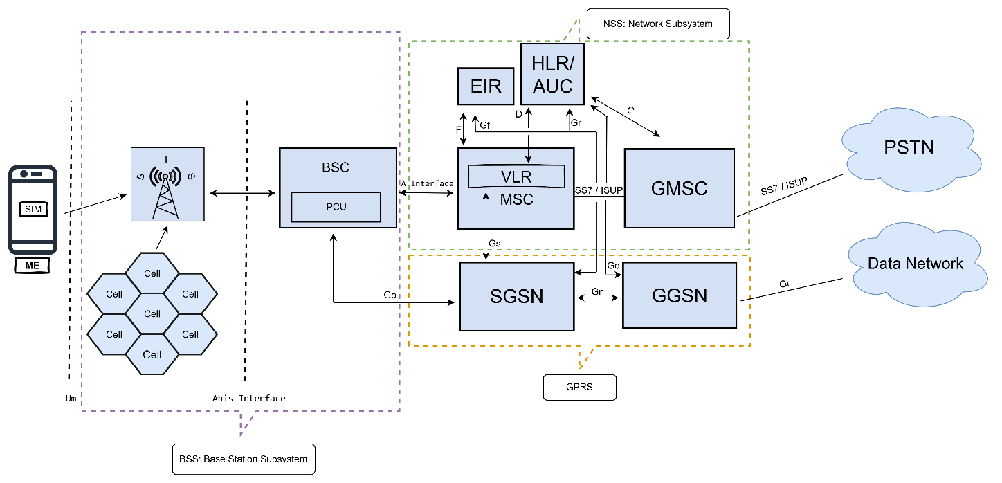
GSM Architecture — Three Subsystems
The handset plus its SIM card. The SIM stores the subscriber's permanent identity (IMSI), secret key (Ki), and authentication algorithms. The handset (Mobile Equipment) is identified separately by its IMEI, checked against the EIR to block stolen devices.
The radio access layer. The BTS (Base Transceiver Station) is the physical antenna — it sends and receives radio signals to/from handsets over the Um interface. The BSC (Base Station Controller) manages multiple BTSs: it controls frequency hopping, handles intra-BSC handovers, and connects the radio layer to the core via the A interface. The PCU (Packet Control Unit) is co-located with the BSC and handles all packet data scheduling on the radio — it splits the GSM voice path from the packet data path right at the BSS boundary.
The intelligence of the network. Key nodes:
- MSC — routes voice calls, manages call state, and interfaces with the PSTN; the GMSC handles incoming calls from outside the network. Packet data never passes through the MSC.
- HLR — the master subscriber database stores your phone number (MSISDN), IMSI, active services, and which VLR you are currently registered with
- VLR — a local cache co-located with the MSC; stores data for all currently attached users so the MSC avoids querying the remote HLR on every call or message
- AUC — generates authentication triplets (RAND, SRES, Kc) used to authenticate subscribers and derive per-session encryption keys
- SGSN — Serving GPRS Support Node; handles mobility, session management, and tunnelling for packet data coming from the PCU
- GGSN — Gateway GPRS Support Node; the edge router that assigns IP addresses and connects the mobile network to the internet or external data networks
Different interfaces are used in the 2G architecture to enable communication between various network components, as shown in the figure. These include the Air Interface (Um), Abis Interface, A Interface, Gb, Gn, Gi, Gr, Gs, F, C, and D interfaces.
Abbreviations
| Abbreviation | Full Form | Abbreviation | Full Form |
|---|---|---|---|
| MS | Mobile Station | BSS | Base Station Subsystem |
| BTS | Base Transceiver Station | NSS | Network Switching Subsystem |
| BSC | Base Station Controller | PSTN | Public Switched Telephone Network |
| PCU | Packet Control Unit | GPRS | General Packet Radio Service |
| MSC | Mobile Switching Center | Um | Air Interface (MS ↔ BTS) |
| VLR | Visitor Location Register | Abis | Interface (BTS ↔ BSC) |
| HLR | Home Location Register | A | Interface (BSC ↔ MSC) |
| AUC | Authentication Center | Gb | Interface (BSC/PCU ↔ SGSN) |
| EIR | Equipment Identity Register | Gs | Interface (SGSN ↔ MSC/VLR) |
| GMSC | Gateway Mobile Switching Center | Gr | Interface (SGSN ↔ HLR) |
| SGSN | Serving GPRS Support Node | Gn | Interface (SGSN ↔ GGSN) |
| GGSN | Gateway GPRS Support Node | Gi | Interface (GGSN ↔ Internet) |
| IMSI | International Mobile Subscriber Identity | C | Interface (GMSC ↔ HLR) |
| IMEI | International Mobile Equipment Identity | D | Interface (MSC/VLR ↔ HLR) |
| SIM | Subscriber Identity Module | F | Interface (MSC ↔ EIR) |
GSM carries voice and packet data on completely separate paths that diverge at the BSC/PCU:
Voice is digitised, channel-coded, and sent as a dedicated circuit through the BSC and MSC to the PSTN. The MSC controls call state for the entire session.
Packet data is handed to the PCU at the BSC, which schedules GPRS radio blocks. The PCU tunnels IP packets to the SGSN over the Gb interface. The SGSN manages mobility and delivers them to the GGSN, which routes them to the internet. The MSC is not involved at any step.
GSM Specification — Radio Access Technology
900 MHz Band
| Bandwidth | 25 MHz |
|---|---|
| Uplink | 890 – 915 MHz |
| Downlink | 935 – 960 MHz |
| Duplex Spacing | 45 MHz |
| ARFCN Spacing | 200 kHz |
| ARFCN Range | 1 – 124 (125 × 200 kHz ≈ 25 MHz) |
| ARFCN 0 | 935.0 MHz (DL) / 890.0 MHz (UL) — Reserved |
| Wavelength | ≈ 0.33 m |
| Duplex Mode | FDD |
1800 MHz Band
| Bandwidth | 74.6 MHz |
|---|---|
| Uplink | 1710.2 – 1784.8 MHz |
| Downlink | 1805.2 – 1879.8 MHz |
| Duplex Spacing | 95 MHz |
| ARFCN Spacing | ≈ 200 kHz |
| ARFCN Range | 512 – 885 (373 × 200 kHz ≈ 74.6 MHz) |
| ARFCN 0 | — |
| Wavelength | ≈ 0.166 m |
| Duplex Mode | FDD |
Note on ARFCN 0: In the original GSM spec (3GPP TS 45.005), ARFCN 0 is technically defined but is not used for traffic in standard GSM 900. It is associated with the E-GSM extension band, not the primary GSM 900 band.
Bandwidth is the range (or width) of frequencies available for transmitting data over a communication channel.
ARFCN (Absolute Radio Frequency Channel Number) — instead of stating raw frequencies like 935.2 MHz, GSM uses ARFCN numbers. For example, ARFCN 1 corresponds to 935.2 MHz.
Data Speeds
| Technology | Speed |
|---|---|
| GSM CSD (Circuit Switched Data) | ≈ 9.6 Kbps |
| GPRS (typical) | 40 – 60 Kbps |
| GPRS (theoretical peak) | 171.2 Kbps |
| EDGE | Up to 384 Kbps |
GSM Call Flow
When a mobile is powered on, it scans the Broadcast Channel (BCCH) to determine the strongest signal and locks onto the appropriate channel (ARFCN).
If the mobile is in a new Location Area (LA), it performs a Location Update. The VLR updates the subscriber's location in the HLR.
- The user dials a number; the MS sends a burst over the Random Access Channel (RACH) using the locked ARFCN.
- The BS responds with an Access Grant, assigns a dedicated channel, and commands the MS to retune to a new ARFCN.
- The BTS/BSC forwards the request to the MSC.
- The MSC checks the subscriber profile in VLR/HLR and completes authentication.
- The MSC responds to BSC/BTS, and the MS initiates call setup.
The MSC determines the route:
- If the call is to the PSTN → route via GMSC
- If the call is to another mobile → locate the destination MSC/VLR
MSC → BSC → BTS sends a Paging Request to all cells in the destination subscriber's location area.
The destination MS responds by identifying itself over the RACH. The BS relays the acknowledgement to the MSC.
An alert message is transmitted over the forward voice channel, instructing the originating mobile to ring. All these events occur within a second and are not noticeable to the user. Once the call is in progress, the MSC adjusts the transmitted power of the mobile and performs handover whenever necessary.
Handover
The transfer of an ongoing call to a new cell or channel when the serving cell's signal quality or strength degrades below a threshold and a neighbouring cell offers better quality. Handover ensures call continuity and always occurs in active mode — while a session is in progress.
Cell Selection / Reselection
The process by which the mobile station autonomously selects the best available cell based on received signal strength and quality. Cell selection occurs at power-on or when leaving coverage; reselection occurs when a neighbouring cell consistently offers better radio conditions. Both processes always occur silently in idle mode, when no active session is in progress.